Technician / Topics
T6 Electronic and Electrical Components
T6 Electronic and Electrical Components (Technician questions)46 questions in 4 groups. The exam asks 4 questions from this topic, one from each group.
T6A Fixed and variable resistors; Capacitors; Inductors; Fuses; Switches; Batteries
T6A01
What electrical component opposes the flow of current in a DC circuit?
- A. Inductor
- B. Resistor
- C. Inverter
- D. Transformer
Show answer
B. Resistor
A resistor is built to oppose the flow of current, in DC and AC circuits alike, turning the energy it absorbs into heat. Its resistance is measured in ohms.
- A. An inductor opposes changes in current, but once a steady DC current flows, it offers only the small resistance of its wire.
- C. An inverter converts DC to AC, for example 12 V DC to 120 V AC; it is not a component for opposing current.
- D. A transformer changes AC voltage levels through magnetic coupling between windings; it does not work on steady DC and is not used to oppose current.
T6A02
What type of component is often used as an adjustable volume control?
- A. Fixed resistor
- B. Power resistor
- C. Potentiometer
- D. Transformer
Show answer
C. Potentiometer
A potentiometer is a variable resistor with a sliding contact (the wiper) that moves along a resistive element. Turning the knob changes how much of the audio signal is passed on, so it is the usual volume control.
- A. A fixed resistor has one resistance value that cannot be adjusted, so it cannot serve as a volume control.
- B. A power resistor is a fixed resistor built to dissipate a lot of heat, not an adjustable control.
- D. A transformer changes AC voltage levels through magnetically coupled windings and has no adjustment for volume.
T6A03
What electrical parameter is controlled by a potentiometer?
- A. Inductance
- B. Resistance
- C. Capacitance
- D. Field strength
Show answer
B. Resistance
A potentiometer is an adjustable resistor. Moving its wiper along the resistive element changes the resistance between the wiper and each end of the element.
- A. Inductance is adjusted with a variable inductor, such as a coil with a movable tap or core, not a potentiometer.
- C. Capacitance is adjusted with a variable capacitor, which changes the overlap or spacing of its plates.
- D. Field strength is the intensity of an electric or magnetic field, such as a radio signal at a location; it is not a parameter a potentiometer sets.
T6A04
What electrical component stores energy in an electric field?
- A. Resistor
- B. Capacitor
- C. Inductor
- D. Diode
Show answer
B. Capacitor
A capacitor stores energy in the electric field between its plates when a voltage is applied across it.
- A. A resistor converts electrical energy into heat; it does not store energy.
- C. An inductor stores energy in a magnetic field, not an electric field.
- D. A diode lets current flow in one direction only; it is not used to store energy.
T6A05
What type of electrical component consists of conductive surfaces separated by an insulator?
- A. Resistor
- B. Potentiometer
- C. Oscillator
- D. Capacitor
Show answer
D. Capacitor
A capacitor is made of two conductive surfaces (plates) separated by an insulator called the dielectric. The insulator blocks steady DC, while charge collects on the plates and stores energy in the electric field between them.
- A. A resistor is made from a material that conducts with some opposition, such as carbon film or resistance wire, not two conductors separated by an insulator.
- B. A potentiometer is a resistive element with a sliding contact, a variable resistor rather than separated conductive surfaces.
- C. An oscillator is a circuit that generates a repeating signal, not a single component made of separated conductive surfaces.
T6A06
What type of electrical component stores energy in a magnetic field?
- A. Resistor
- B. Capacitor
- C. Inductor
- D. Diode
Show answer
C. Inductor
An inductor, usually a coil of wire, stores energy in the magnetic field created by the current flowing through it.
- A. A resistor converts electrical energy into heat rather than storing it.
- B. A capacitor stores energy in an electric field, not a magnetic field.
- D. A diode passes current in one direction only and does not store energy in a magnetic field.
T6A07
What electrical component is typically constructed as a coil of wire?
- A. Transistor
- B. Capacitor
- C. Diode
- D. Inductor
Show answer
D. Inductor
An inductor is typically a coil of wire, sometimes wound on an iron or ferrite core. Coiling the wire concentrates its magnetic field and increases the inductance.
- A. A transistor is built from regions of semiconductor material, not a coil of wire.
- B. A capacitor is made of conductive plates separated by an insulator.
- C. A diode is a junction between two types of semiconductor material.
T6A08
What is the function of an SPDT switch?
- A. A single circuit is opened or closed
- B. Two circuits are opened or closed
- C. A single circuit is switched between one of two other circuits
- D. Two circuits are each switched between one of two other circuits
Show answer
C. A single circuit is switched between one of two other circuits
SPDT means single-pole double-throw. Single pole means one circuit is switched; double throw means that circuit can be connected to either of two other circuits, like a switch that selects between two antennas.
- A. Opening or closing a single circuit describes a single-pole single-throw (SPST) switch, such as a basic on/off switch.
- B. Opening or closing two circuits at once describes a double-pole single-throw (DPST) switch.
- D. Switching two circuits, each between two other circuits, describes a double-pole double-throw (DPDT) switch.
T6A09
What type of switch is represented by component 3 in figure T-2?
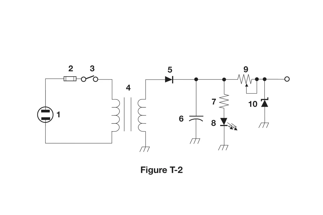
Figure T-2 - A. Single-pole single-throw
- B. Single-pole double-throw
- C. Double-pole single-throw
- D. Double-pole double-throw
Show answer
A. Single-pole single-throw
Component 3 in figure T-2 is drawn as one hinged blade and one contact that the blade can close against. That is one switched circuit (single pole) with one closed position (single throw): a single-pole single-throw (SPST) on/off switch, here in series with the fuse on the input side of the transformer.
- B. A single-pole double-throw switch would show one blade that can swing to either of two separate contacts; component 3 has only one contact to close against.
- C. A double-pole single-throw switch would show two blades, usually linked by a dashed line, opening or closing two circuits together.
- D. A double-pole double-throw switch would show two linked blades, each with two contacts to choose between.
T6A10
Which of the following battery chemistries is rechargeable?
- A. Nickel-metal hydride
- B. Lithium-ion
- C. Lead-acid
- D. All these choices are correct
Show answer
D. All these choices are correct
Nickel-metal hydride, lithium-ion, and lead-acid are all rechargeable (secondary) battery chemistries. Each can be recharged many times by driving current back through the cells with a charger.
- A. Nickel-metal hydride is rechargeable and common in AA and AAA rechargeable cells, but it is only one of the rechargeable chemistries listed.
- B. Lithium-ion is rechargeable and powers many handheld radios, but it is only one of the rechargeable chemistries listed.
- C. Lead-acid is rechargeable and used in car batteries and station backup power, but it is only one of the rechargeable chemistries listed.
T6A11
Which of the following battery chemistries is not rechargeable?
- A. Nickel-cadmium
- B. Carbon-zinc
- C. Lead-acid
- D. Lithium-ion
Show answer
B. Carbon-zinc
Carbon-zinc cells are primary cells: the chemical reaction that produces their current is not designed to be reversed, so they are discarded when depleted and should not be put on a charger.
- A. Nickel-cadmium is a rechargeable chemistry, once common in handheld radio battery packs.
- C. Lead-acid batteries are rechargeable; car batteries and many station backup batteries use this chemistry.
- D. Lithium-ion batteries are rechargeable and are widely used in handheld radios, phones, and laptops.
T6B Semiconductors: basic principles and applications of solid-state devices, diodes and transistors; Gain
T6B01
Which is true about forward voltage drop in a diode?
- A. It is lower in some diode types than in others
- B. It is proportional to peak inverse voltage
- C. It indicates that the diode is defective
- D. It has no impact on the voltage delivered to the load
Show answer
A. It is lower in some diode types than in others
Forward voltage drop is the voltage across a diode while it conducts, and it depends on the diode type. Germanium and Schottky diodes drop roughly 0.2 to 0.4 V, a silicon diode about 0.7 V, and an LED more than that.
- B. Peak inverse voltage is the highest reverse voltage a diode can withstand; it is a separate rating that does not set the forward voltage drop.
- C. Every working diode has a forward voltage drop while conducting; it is a normal property, not a sign of a fault.
- D. The forward voltage drop subtracts from the voltage reaching the load; a conducting silicon rectifier leaves about 0.7 V less for the load.
T6B02
What electronic component allows current to flow in only one direction?
- A. Resistor
- B. Fuse
- C. Diode
- D. Driven element
Show answer
C. Diode
A diode conducts when forward biased (anode more positive than cathode) and blocks current when reverse biased, so current flows in only one direction. Rectifiers use this property to convert AC to DC.
- A. A resistor opposes current equally in both directions.
- B. A fuse passes current in both directions and opens the circuit if the current becomes too high, protecting the equipment.
- D. A driven element is the part of an antenna connected to the feed line, not a component that controls the direction of current.
T6B03
Which of these components can be used as an electronic switch?
- A. Varistor
- B. Potentiometer
- C. Transistor
- D. Thermistor
Show answer
C. Transistor
A transistor uses a small current or voltage at one terminal (the base or gate) to turn a larger current on or off between its other terminals. That lets it act as an electronic switch as well as an amplifier.
- A. A varistor is a voltage-dependent resistor used to absorb voltage surges, not to switch circuits on command.
- B. A potentiometer is a manually adjusted variable resistor, not an electronic switch.
- D. A thermistor is a resistor whose resistance changes with temperature, used for temperature sensing and compensation.
T6B04
Which of the following components can consist of three regions of semiconductor material?
- A. Alternator
- B. Transistor
- C. Triode
- D. Pentode
Show answer
B. Transistor
A bipolar junction transistor is made of three regions of semiconductor material, arranged NPN or PNP, which form its emitter, base, and collector.
- A. An alternator is a rotating machine that generates AC, built from coils and magnets rather than semiconductor regions.
- C. A triode is a vacuum tube with three electrodes (cathode, grid, and plate), not three regions of semiconductor material.
- D. A pentode is a vacuum tube with five electrodes, not a semiconductor device.
T6B05
What type of transistor has a gate, drain, and source?
- A. Varistor
- B. Field-effect
- C. Hall-effect
- D. Bipolar junction
Show answer
B. Field-effect
A field-effect transistor (FET) has a gate, a drain, and a source. The voltage on the gate creates an electric field that controls the current flowing between the source and the drain.
- A. A varistor is a voltage-dependent resistor with two leads, not a transistor.
- C. A Hall-effect device is a sensor that responds to magnetic fields; its terminals are not called gate, drain, and source.
- D. A bipolar junction transistor has an emitter, a base, and a collector instead.
T6B06
How is the cathode lead of a semiconductor diode often marked on the package?
- A. With the word "cathode"
- B. With a stripe
- C. With the letter C
- D. With the letter K
Show answer
B. With a stripe
The cathode end of a diode is usually marked with a band, or stripe, around the package. This matches the schematic symbol, where a bar at the point of the triangle marks the cathode.
- A. Diodes are not normally labeled with the word "cathode"; the standard cathode marking is a stripe on the package.
- C. Diode packages are not normally marked with a C; the stripe is the standard cathode marking.
- D. K is sometimes used for the cathode in schematic labels and data sheets, but the package itself is normally marked with a stripe.
T6B07
What causes a light-emitting diode (LED) to emit light?
- A. Forward current
- B. Reverse current
- C. Capacitively-coupled RF signal
- D. Inductively-coupled RF signal
Show answer
A. Forward current
An LED emits light when forward current flows through its semiconductor junction: electrons crossing the junction release energy as light. A reverse-biased LED blocks current and stays dark.
- B. A reverse-biased LED blocks current and does not emit light; too much reverse voltage can damage it.
- C. Capacitive coupling of an RF signal is not how an LED produces light; it needs forward current through its junction.
- D. Inductive coupling of an RF signal is not how an LED produces light; it needs forward current through its junction.
T6B08
What does the abbreviation FET stand for?
- A. Frequency Emission Transmitter
- B. Fast Electron Transistor
- C. Free Electron Transmitter
- D. Field Effect Transistor
Show answer
D. Field Effect Transistor
FET stands for field-effect transistor, a transistor in which the voltage on the gate sets up an electric field that controls the current between the source and the drain.
- A. Frequency Emission Transmitter is not a real term; the T in FET stands for transistor.
- B. Fast Electron Transistor is not a real device; the F and E stand for field effect.
- C. Free Electron Transmitter is not a real term; a FET is a component, not a transmitter.
T6B09
What are the names for the electrodes of a diode?
- A. Plus and minus
- B. Source and drain
- C. Anode and cathode
- D. Gate and base
Show answer
C. Anode and cathode
A diode's two electrodes are the anode and the cathode. Current flows from the anode to the cathode when the diode is forward biased (anode more positive than cathode).
- A. Plus and minus label the terminals of a power source such as a battery, not the electrodes of a diode.
- B. Source and drain are two of the electrodes of a field-effect transistor.
- D. Gate is a field-effect transistor electrode and base is a bipolar transistor electrode; neither belongs to a diode.
T6B10
Which of the following can provide power gain?
- A. Transformer
- B. Transistor
- C. Reactor
- D. Resistor
Show answer
B. Transistor
A transistor can provide power gain: a small input signal controls a larger current drawn from the power supply, so the output signal has more power than the input signal.
- A. A transformer can step voltage up or down, but the current changes in the opposite proportion, so its output power is never more than its input power.
- C. A reactor is a component used for its reactance, usually an inductor; it stores and returns energy but cannot add power to a signal.
- D. A resistor only dissipates power as heat; it cannot make a signal stronger.
T6B11
What does the term gain mean in amplifiers?
- A. The output signal voltage relative to the input signal voltage
- B. The output signal current relative to the input signal current
- C. The output signal power relative to the input signal power
- D. All these choices are correct
Show answer
D. All these choices are correct
Gain is the ratio of an amplifier's output signal to its input signal. It can be stated for voltage, current, or power, and is often expressed in decibels.
- A. Voltage gain (output voltage relative to input voltage) is a valid meaning of gain, but current gain and power gain are as well, so this is only part of the answer.
- B. Current gain (output current relative to input current) is a valid meaning of gain, but voltage gain and power gain are as well, so this is only part of the answer.
- C. Power gain (output power relative to input power) is a valid meaning of gain, but voltage gain and current gain are as well, so this is only part of the answer.
T6B12
What are the names of the electrodes of a bipolar junction transistor?
- A. Signal, bias, power
- B. Emitter, base, collector
- C. Input, output, supply
- D. Pole one, pole two, output
Show answer
B. Emitter, base, collector
A bipolar junction transistor (BJT) has three electrodes: the emitter, the base, and the collector. A small current into the base controls a larger current between the collector and the emitter.
- A. Signal, bias, and power describe what is applied to a circuit, not the names of transistor electrodes.
- C. Input, output, and supply describe circuit connections in general, such as the pins of a voltage regulator, not the electrodes of a BJT.
- D. Pole is a term used for switch contacts, not transistor electrodes.
T6C Circuit diagrams: use of term schematic, basic structure; Schematic symbols of basic components
T6C01
What is an electrical diagram using standard component symbols called?
- A. Connection chart
- B. Instrumentation system
- C. Schematic
- D. Flow chart
Show answer
C. Schematic
A schematic diagram uses standard symbols for components and lines for the connections between them. It shows how a circuit is wired electrically, not how it looks physically.
- A. Connection chart is not the name for a diagram drawn with standard component symbols.
- B. An instrumentation system is a set of measuring equipment, not a diagram.
- D. A flow chart shows the steps of a process or program with boxes and arrows, not electrical components.
T6C02
What is component 1 in figure T-1?
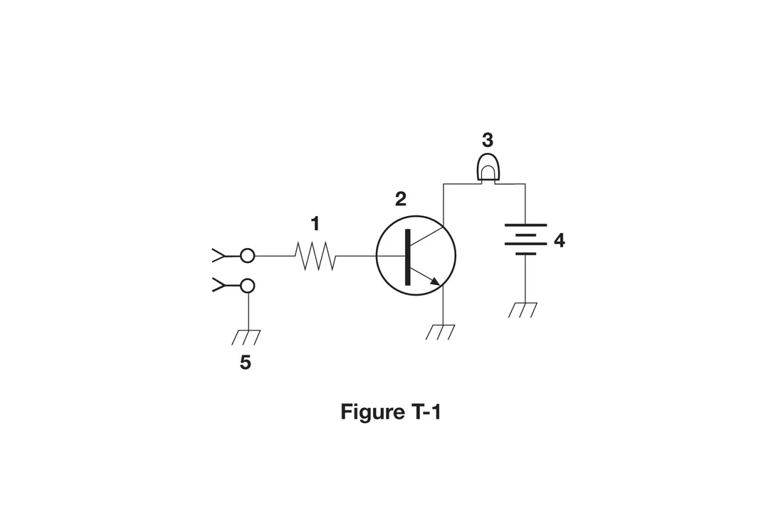
Figure T-1 - A. Resistor
- B. Transistor
- C. Battery
- D. Connector
Show answer
A. Resistor
Component 1 in figure T-1 is a zigzag line, the schematic symbol for a resistor. Here it limits the current flowing from the input connector into the base of the transistor.
- B. The transistor in figure T-1 is component 2, the circle containing a thick bar with two angled lines, one with an arrow.
- C. The battery in figure T-1 is component 4, the stack of parallel lines alternating long and short.
- D. The connectors in figure T-1 are the small circles with forked ends at the far left, where the input signal enters.
T6C03
What is component 2 in figure T-1?
Figure T-1 - A. Resistor
- B. Transistor
- C. Indicator lamp
- D. Connector
Show answer
B. Transistor
Component 2 in figure T-1 is a circle containing a thick bar (the base) with two angled lines (the collector and the emitter), the symbol for a bipolar junction transistor. The arrow on the emitter points outward, which marks an NPN transistor.
- A. The resistor in figure T-1 is component 1, the zigzag line.
- C. The indicator lamp in figure T-1 is component 3, the rounded bulb outline with a loop inside.
- D. The connectors in figure T-1 are the small circles with forked ends at the far left.
T6C04
What is component 3 in figure T-1?
Figure T-1 - A. Resistor
- B. Transistor
- C. Lamp
- D. Ground symbol
Show answer
C. Lamp
Component 3 in figure T-1 is a rounded bulb outline with a filament loop inside, the symbol for an incandescent lamp. In this circuit, the transistor switches current from the battery through the lamp.
- A. The resistor in figure T-1 is component 1, the zigzag line.
- B. The transistor in figure T-1 is component 2, the circle with a thick bar and two angled lines, one with an arrow.
- D. The ground symbols in figure T-1 are the short lines with slanted hash marks at the bottom, such as the one labeled 5.
T6C05
What is component 4 in figure T-1?
Figure T-1 - A. Resistor
- B. Transistor
- C. Ground symbol
- D. Battery
Show answer
D. Battery
Component 4 in figure T-1 is a stack of parallel lines alternating long and short, the symbol for a battery. Each long and short pair represents one cell, and the long line marks the positive side.
- A. The resistor in figure T-1 is component 1, the zigzag line.
- B. The transistor in figure T-1 is component 2, the circle with a thick bar and two angled lines, one with an arrow.
- C. A ground symbol is drawn with slanted hash marks, as at component 5; component 4 is parallel lines of alternating length.
T6C06
What is component 6 in figure T-2?
Figure T-2 - A. Resistor
- B. Capacitor
- C. Regulator IC
- D. Transistor
Show answer
B. Capacitor
Component 6 in figure T-2 is two plates separated by a small gap (one drawn straight, one curved), the symbol for a capacitor. In this power supply it is the filter capacitor that smooths the pulsating DC from the rectifier diode.
- A. A resistor is drawn as a zigzag line, such as component 7 in figure T-2.
- C. A regulator IC would be drawn as a box with labeled terminals; component 6 is a pair of plates.
- D. A transistor is drawn as a bar with angled lines and an arrow, usually inside a circle; figure T-2 has no transistor.
T6C07
What is component 8 in figure T-2?
Figure T-2 - A. Resistor
- B. Inductor
- C. Regulator IC
- D. Light emitting diode
Show answer
D. Light emitting diode
Component 8 in figure T-2 is a diode symbol (a triangle pointing at a bar) with arrows pointing away from it, which show emitted light: a light-emitting diode. With resistor 7 limiting its current, it serves as a power indicator.
- A. The resistor is component 7, the zigzag line directly above the LED, which limits its current.
- B. An inductor is drawn as a row of loops, like the windings of the transformer at component 4.
- C. A regulator IC would be drawn as a box with labeled terminals; component 8 is a diode symbol with light arrows.
T6C08
What is component 9 in figure T-2?
Figure T-2 - A. Variable capacitor
- B. Variable inductor
- C. Variable resistor
- D. Variable transformer
Show answer
C. Variable resistor
Component 9 in figure T-2 is a zigzag resistor symbol with an arrow touching it, the symbol for a variable resistor; the arrow represents the movable contact. Here the arrow is connected to one end, so the part works as a two-terminal adjustable resistance.
- A. A variable capacitor is drawn as two plates with a diagonal arrow through them, as at component 2 in figure T-3.
- B. A variable inductor is drawn as a row of loops with an arrow, as at component 3 in figure T-3.
- D. A variable transformer would show coupled windings with an adjustable tap; component 9 is a zigzag resistor element.
T6C09
What is component 4 in figure T-2?
Figure T-2 - A. Variable inductor
- B. Double-pole switch
- C. Potentiometer
- D. Transformer
Show answer
D. Transformer
Component 4 in figure T-2 shows two coils side by side with parallel lines between them, the symbol for a transformer with an iron core. It couples AC from the input circuit on the left to the rectifier circuit on the right while changing the voltage.
- A. A variable inductor is a single coil with an arrow or adjustable tap; component 4 is two coils sharing a core.
- B. A double-pole switch would show two linked blades; the only switch in figure T-2 is component 3, a single-pole single-throw switch.
- C. A potentiometer is drawn as a zigzag resistor with an arrow for its wiper, similar to component 9.
T6C10
What is component 3 in figure T-3?
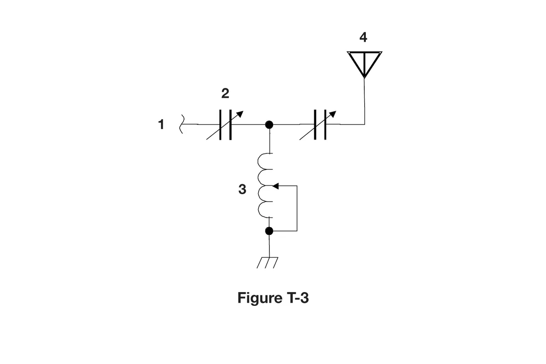
Figure T-3 - A. Connector
- B. Meter
- C. Variable capacitor
- D. Variable inductor
Show answer
D. Variable inductor
Component 3 in figure T-3 is a row of loops (an inductor) with an arrow touching it, showing an adjustable connection, the symbol for a variable inductor. With the two variable capacitors, it forms a T-network antenna tuner.
- A. A connector is drawn as a small circle or plug shape at the end of a line; component 3 is a coil.
- B. A meter is drawn as a circle with a letter or label inside, such as A for an ammeter or V for a voltmeter.
- C. The variable capacitors in figure T-3 are the pairs of parallel plates with a diagonal arrow, such as component 2.
T6C11
What is component 4 in figure T-3?
Figure T-3 - A. Antenna
- B. Transmitter
- C. Dummy load
- D. Ground
Show answer
A. Antenna
Component 4 in figure T-3 is a vertical line topped by a downward-pointing triangle, the schematic symbol for an antenna. The circuit is an antenna tuner that matches the line at point 1 to this antenna.
- B. A transmitter is not drawn with this symbol; in figure T-3 the input line at point 1 is where a transmitter would connect.
- C. A dummy load is a resistor that absorbs power without radiating, drawn with a resistor symbol, not the antenna symbol.
- D. The ground in figure T-3 is the symbol with slanted hash marks below the coil.
T6C12
Which of the following is accurately represented in electrical schematics?
- A. Wire lengths
- B. Physical appearance of components
- C. Component connections
- D. All these choices are correct
Show answer
C. Component connections
A schematic accurately shows how components are connected electrically, which is what matters for understanding and building a circuit. It does not show wire lengths, physical layout, or what the parts look like.
- A. A line on a schematic shows only that two points are connected; its drawn length says nothing about the real wire length.
- B. Schematic symbols are standard drawings that represent a component's function, not its real shape or size.
- D. Only component connections are accurately represented; wire lengths and physical appearance are not.
T6D Component functions: rectifiers, relays, voltage regulators, meters, indicators, integrated circuits, transformers; Resonant circuit; Shielding
T6D01
Which of the following devices or circuits changes an alternating current into a varying direct current signal?
- A. Transformer
- B. Rectifier
- C. Amplifier
- D. Reflector
Show answer
B. Rectifier
A rectifier, built from one or more diodes, passes current in only one direction, turning alternating current into pulsating (varying) direct current. In a power supply, a filter capacitor then smooths it into steadier DC.
- A. A transformer changes the voltage of AC, but its output is still AC.
- C. An amplifier increases the strength of a signal; it does not convert AC into DC.
- D. A reflector is a parasitic element of a beam antenna, not a circuit that converts current.
T6D02
What is a relay?
- A. An electrically-controlled switch
- B. A current-controlled amplifier
- C. An inverting amplifier
- D. A pass transistor
Show answer
A. An electrically-controlled switch
A relay is a switch operated by an electromagnet. Current through the relay's coil pulls its contacts open or closed, so a small control current can switch a separate, often larger, circuit, for example to change an antenna between transmitter and receiver.
- B. A current-controlled amplifier describes a bipolar transistor, which can vary its output smoothly; a relay only opens or closes its contacts.
- C. An inverting amplifier produces an amplified, inverted copy of its input signal; a relay does not amplify.
- D. A pass transistor is the series transistor in a voltage regulator that carries the load current; it is not a relay.
T6D03
Which of the following is a reason to use shielded wire?
- A. To decrease the resistance of DC power connections
- B. To increase the current carrying capability of the wire
- C. To prevent coupling of unwanted signals to or from the wire
- D. To reduce receiver overload
Show answer
C. To prevent coupling of unwanted signals to or from the wire
Shielded wire has a conductive braid or foil around the inner conductors, usually connected to ground. The shield keeps unwanted signals from coupling into the wire and keeps signals on the wire from radiating out and interfering with other equipment.
- A. A shield does not lower the resistance of the inner conductor; heavier wire does that.
- B. Current carrying capability depends on the conductor size and its insulation, not on a shield.
- D. Receiver overload is caused by strong signals at the receiver input, usually arriving through the antenna, and is treated with filters or attenuators rather than shielded wire.
T6D04
Which of the following displays an electrical quantity as a numeric value?
- A. Potentiometer
- B. Transistor
- C. Meter
- D. Relay
Show answer
C. Meter
A meter measures an electrical quantity such as voltage, current, or resistance and displays its value. A digital meter shows the value as numbers on a display.
- A. A potentiometer is an adjustable resistor and has no display.
- B. A transistor amplifies or switches signals; it does not display values.
- D. A relay is an electrically operated switch and does not display anything.
T6D05
What type of circuit controls the amount of voltage from a power supply?
- A. Regulator
- B. Oscillator
- C. Filter
- D. Phase inverter
Show answer
A. Regulator
A voltage regulator holds a power supply's output voltage at a set value even as the input voltage or the load current changes.
- B. An oscillator generates a repeating signal at a set frequency; it does not control supply voltage.
- C. A filter passes some frequencies and blocks others; in a power supply it smooths ripple but does not hold the output at a set voltage.
- D. A phase inverter produces a signal 180 degrees out of phase with its input; it does not control supply voltage.
T6D06
What component changes 120 V AC power to a lower AC voltage for other uses?
- A. Variable capacitor
- B. Transformer
- C. Transistor
- D. Diode
Show answer
B. Transformer
A transformer has two or more windings coupled through a shared magnetic core. AC in the primary winding induces AC in the secondary, and the ratio of turns sets the output voltage, so a secondary with fewer turns steps 120 V AC down to a lower AC voltage.
- A. A variable capacitor is used to tune circuits, not to convert AC power from one voltage to another.
- C. A transistor amplifies or switches signals; it does not convert AC line voltage to a lower AC voltage the way a transformer does.
- D. A diode passes current in one direction, turning AC into pulsating DC rather than a lower AC voltage.
T6D07
Which of the following is commonly used as a visual indicator?
- A. LED
- B. FET
- C. Zener diode
- D. All these choices are correct
Show answer
A. LED
A light-emitting diode (LED) glows when forward current flows through it and uses little power, so it is widely used as a visual indicator for power-on, transmit, and similar status lights.
- B. A FET is a field-effect transistor used to amplify or switch signals; it does not emit light.
- C. A Zener diode is used for voltage regulation, conducting in reverse at a fixed voltage; it does not emit light.
- D. Only the LED gives off light; FETs and Zener diodes are not visual indicators, so not all the choices are correct.
T6D08
Which of the following is combined with an inductor to make a resonant circuit?
- A. Resistor
- B. Zener diode
- C. Potentiometer
- D. Capacitor
Show answer
D. Capacitor
An inductor and a capacitor together form a resonant (tuned) circuit. At the resonant frequency, the inductor's reactance equals the capacitor's reactance, and energy moves back and forth between the inductor's magnetic field and the capacitor's electric field.
- A. A resistor has no reactance and does not store energy, so it cannot form a resonant circuit with an inductor; it only adds loss.
- B. A Zener diode is a voltage regulating device, not a reactive component used for tuning.
- C. A potentiometer is a variable resistor; like any resistor, it does not store energy and cannot produce resonance with an inductor.
T6D09
What is the name of a device that combines several semiconductors and other components into one package?
- A. Transducer
- B. Multi-pole relay
- C. Integrated circuit
- D. Transformer
Show answer
C. Integrated circuit
An integrated circuit (IC) combines many transistors, diodes, resistors, and other components on one chip in a single package. Voltage regulators, operational amplifiers, and microprocessors are common examples.
- A. A transducer converts one form of energy into another, such as a microphone turning sound into an electrical signal.
- B. A multi-pole relay is an electrically controlled switch with several sets of contacts, not a package of semiconductors.
- D. A transformer is made of coupled windings on a core and contains no semiconductors.
T6D10
What is the function of component 2 in figure T-1?
Figure T-1 - A. Give off light when current flows through it
- B. Supply electrical energy
- C. Control the flow of current
- D. Convert electrical energy into radio waves
Show answer
C. Control the flow of current
Component 2 in figure T-1 is a transistor. A small current through resistor 1 into its base controls a much larger current from the battery (component 4) through the lamp (component 3), so the transistor controls the flow of current.
- A. Giving off light is the job of component 3, the lamp.
- B. Supplying electrical energy is the job of component 4, the battery.
- D. Converting electrical energy into radio waves is the job of an antenna, which does not appear in figure T-1.
T6D11
Which of the following is a resonant or tuned circuit?
- A. An inductor and a capacitor in series or parallel
- B. A linear voltage regulator
- C. A resistor circuit used for reducing standing wave ratio
- D. A circuit designed to provide high-fidelity audio
Show answer
A. An inductor and a capacitor in series or parallel
A resonant, or tuned, circuit is an inductor and a capacitor connected in series or in parallel. It responds strongly at the frequency where the inductive and capacitive reactances are equal, which makes it useful for selecting one frequency.
- B. A linear voltage regulator holds a DC voltage steady; it is not tuned to a frequency.
- C. Resistors have no reactance, so a resistor circuit cannot be resonant; resistive networks absorb power rather than tune.
- D. A high-fidelity audio circuit is designed to pass a wide range of frequencies evenly, the opposite of a tuned circuit that favors one frequency.